Rear disc brake pads offer better performance and are not as affected by moisture like conventional brake shoe style brakes are. Rear disc brakes are similar to front disc brakes. The main difference is that rear disc brake systems must incorporate the emergency brake system. There are two methods widely used for the emergency brake with rear disc systems. The first system is a brake shoe inside the brake disc that is actuated by the emergency brake lever. The second is a screw style actuator inside the brake caliper. When activated the brake pads are forced into the brake disc and held tightly by the emergency brake lever.
Step 1: Identify Rear Disc Brake Components

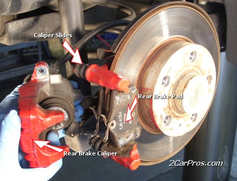
Rear Disc Brake Identification
Rear disc brake assembly includes; rear brake disc, rear brake pads, brake caliper mount and a caliper mounting screw. (Note: Some vehicles do not have the rotor mounting screw.)
Step 2: Removing the Rear Brake Caliper Mount Bolts


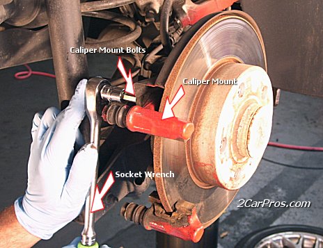
Locate Rear Caliper Mount Bolts
To replace rear brake pads and rotors the rear brake caliper needs to be removed. First loosen the rear brake caliper mount bolts and remove them. Turn counter clockwise.
Step 3: Lift Rear Brake Caliper from The Caliper Mount

Remove Rear Caliper
After the caliper mount bolts have been removed, gently lift the brake caliper from the caliper mount. Inspect the caliper slides; they should move freely in the caliper mount. Remove rear brake pads and hardware.
Step 4: Removing Caliper Mount Bolts

Remove Rear Caliper Mount Bolts
With a socket wrench or other appropriate removal tool, loosen the rear brake caliper mounting bolts. Remove bolts and lift the caliper mount and remove it from the vehicle. Remove the retaining screw from the disc mounting hole. Tap the rotor gently to release any rust that has accumulated between the rotor and bearing hub. Lift brake rotor from wheel hub holding on tightly, using both hands. You do not want to drop the rotor.
Step 5: Removing Rear Brake Rotor


Remove Rear Brake Rotor
Remove the retaining screw from the disc mounting hole, tap the rotor gently to release any rust that has accumulated between the rotor and bearing hub. Lift brake rotor from wheel hub, hold on using both hands and do not drop.
Step 6: Install New Brake Rotor


Replace Rear Brake Rotor
Check the new rotor against the old brake rotor to make sure they are the same size. Clean the mating surface on the wheel hub before the new brake rotor is installed. Reinstall rotor retainer screw.
Step 7: Reset Rear Brake Caliper


Using a Rear Caliper Reset Tool
Before new brake pads can be installed, the rear brake caliper must be reset. The reset tool winds the piston back into position so the new brake pads will fit. This style of brake caliper will not compress with a clamp tool; it can only be reset with the proper reset tool.
Step 8: Reinstall Rear Caliper Mount and Install New Rear Brake Pads


Reinstall Rear Caliper Mount with New Rear Brake Pads
After the caliper has been reset, reinstall caliper mounting bolts and make sure the bolts are tight. Then match up the old brake pads to the new brake pads. They should be exactly the same except, of course; the old ones will be worn out. Check the new brake pads for proper fit and install any brake hardware that is required.
Step 9: Remount Rear Brake Caliper


Reinstall Rear Brake Caliper
Reinstall the brake caliper, align brake pad hardware and reinstall caliper mounting bolts. (Note: align the rear peg of the brake pad to the groove in the caliper piston.) Recheck and retighten all caliper and caliper mount bolts. Bleed brake system to relieve any air in the system. Before driving the vehicle, push the brake pedal down and let it up slowly. This operation forces the brake pads to travel to the brake rotors. DO NOT DRIVE VEHICLE until proper brake pedal operation resumes. When test driving vehicle listen for any unusual noises during the operation of the brakes.======================================================================================
Another Solution For You
Tools Needed:
1. 10mm (rear), 13mm (front), and 18mm (front) sockets
2. 1/2" drive (for 18mm socket) and Breaker bar
3. 3 Pound rubber mallet
4. 18" pry bar
5. Steel and brass wire brushes
6. CRC Disc Brake quiet
7. CRC Synthetic Brake & Caliper grease
8. 8" C-Clamp
9. Patience
1. The best way to do a complete and safe job is put the entire truck on jack stands:
2. Tires removed and old equipment still on.
3. Find the two 18mm outer bolts (attached to the caliper/bracket) and break loose with 1/2" socket and breaker bar. Once the bolts are removed, use pry bar and flat head screw driver to gently pry off the caliper from the brake pad carrier. (This is much easier than trying to remove the entire assembly together).
4. Hang the caliper by a wire (do not let it hang by the brake line itself). Once removed, remove the two 13mm bolts (they have rubber boots on them) from the brake pad carrier. Once these are removed, slowly "walk" the carrier off the rotor. Be very carful not to let the two locater clips (springs) pop off while doing this.
5. Once caliper and pad carrier are off, rotor should come right off. Clean up hub in preparation for new rotor.
6. Ford stock rotors and new rotors
7. Ford pads (left) and new ceramic pads (right)
8. Place a thin layer of CRC Synthetic Brake & Caliper grease on the hub before installing new rotor. This only need to be done to the front rotors.
9. Gently install new rotor and tighten it down with 3 lug nuts in preparation for the reinstall of caliper housing.
10. Clean caliper housing with brass brush to remove all brake dust (paint at this time, if you want to). Slowly and evenly (using old brake pad) compress the caliper pistons in. There is no need to remove the master cylinder cap because there is a built in vent.
11. Once compressed back, they should be even and flush with the housing.
12. At this time, clean the face of them and apply a thin coat of CRC Disc Brake Quiet. Once the new pads are installed in the brake pad carrier, gently slide it in to place, within the caliper.
13. Reinstall the caliper (with the brake pad carrier) on the new rotor tightening the 18mm bolts first (to the brackets), then tighten the 13mm brake pad carrier bolts.
14. This is the rear brake housing. There are two 10mm bolts the hold the rear caliper in place. Remove those bolts and hang the caliper or set on something so it is not hanging by the brake line. Remove rotor - this CAN BE a real "job". The E-Brake pads were holding the rotor on and I had to use a 3 pound rubber mallet and a couple of good swings to remove the old rotor. Once removed, clean up all the parts with the wire brushes.
15. You can see the E-Brake shoes here. See how they are not totally retracted? There is a star wheel at the bottom of the housing for the E-Brakes. Adjust it so the shoes are all the way in, in preparation for the installation of new rotor.
16. Replacement of the rear brake pads are pretty simple. Again, slowly compress the single piston back in so it is smooth with the housing, and install the new pads. One of them "snaps" in to the actual middle of the piston (rear brakes are one piston) and the other pad "snaps in to place on the housing.
17. Stock Ford Rotor and new rotor. Once you have installed the new pads in to the caliper unit, slide the new rotor in to place. If it does not slide on, check to make sure the E-brake is completely retracted by adjusting the star wheel on the bottom of the housing. Using the 10mm bolts, reinstall the calipers.
18. Finished brake job. Before you go ANYWHERE, start truck and pump brakes or you will have NO brakes to start with. Push and release E-Brake a few times so it will "self adjust" itself.